ARM 7 LPC2138 interfacing Programming LCD


The following program is interfacing of LCD with LPC2138 & is simulated on Proteus and working correct.
- I want know what is difference between "|=" and "&=" and "|" operators used on line 50 and 51 and 33.Meaning of both is assign or something else?
- Also I am a beginner in ARM C programming. So can you suggest me a good book about ARM C programming? or a free tutorial on web, will also be appreciated.
- Also the program is for 8 bit interfacing of LCD. How do I convert it to work for 4-bit configuration of LCD?
- One more, How to calculate delay for LPC2138? In program taken count is "19999" means how many seconds? Can any one show calculations?
- Last one, on line 24, why it is 0x80 + 0x40, How it will go on 2'nd line of LCD
Program is taken from http://goo.gl/mfZT3Q
Thanks in advance.
/*
 Connections from LPC2148 to LCD Module:
 P0.0 to P0.7 used as Data bits.
 P1.16 connected to pin4 i.e. RS    - Command / Data
 P1.17 connected to pin6 i.e. E - Enable
 Pin5 of LCD Module i.e. 'R/W' connected to ground
*/

#include<lpc213x.h>


void initLCD(void);
void enable(void);
void LCD_WriteChar(char c);
void LCD_WriteString(char * string);
void LCD_Cmd(unsigned int cmd);
void delay(void);


int main(void)
{
    initLCD(); 					//LCD Now intialized and ready to Print!
    LCD_WriteString(" Welcome to ");
    LCD_Cmd(0x80 + 0x40); 		//Come to 2nd Row
    LCD_WriteString("World of ARM");
    while(1); 					// Loop forever
    return 0; 					//This won't execute :P
}

void initLCD(void)
{
    IODIR0 = 0xFF; 				//P0.0 to P0.7 configured as Output - Using 8 Bit mode
    IODIR1 = (1<<16) | (1<<17);        //P1.16 and P1.17 configured as Output - Control Pins
    IOPIN0 = 0x0; 				//Reset Port0 to 0.
    IOPIN1 = 0x0; 				//Reset Port1 to 0 - Which also makes RS and Enable LOW.

    							//LCD Initialization Sequence Now starts
    delay(); 					//Initial Delay
    LCD_Cmd(0x3C); 			//Function Set Command : 8 Bit Mode , 2 Rows , 5x10 Font Style
    LCD_Cmd(0x0F); 			//Display Switch Command : Display on , Cursor on , Blink on
    LCD_Cmd(0x06); 			//Input Set : Increment Mode
    LCD_Cmd(0x01); 			//Screen Clear Command , Cursor at Home
    LCD_Cmd(0x80); 			//Not required the 1st time but needed to reposition the cursor at home after Clearing Screen
    							//Done!
}

void enable(void)
{
    delay();
    IOPIN1 |=  (1<<17);//Enable=High
    delay();
    IOPIN1 &= ~(1<<17);//Enable=Low
    delay();
}

void LCD_WriteChar(char c)
{
    IOPIN1 |= (1<<16); //Switch to Data Mode
    IOPIN0 = (int) c; //Supply Character Code
    enable(); //Pulse Enable to process it
}

void LCD_WriteString(char * string)
{
    int c=0;
    while (string[c]!='\0')
    {
        LCD_WriteChar(string[c]);
        c++;
    }
}

void LCD_Cmd(unsigned int cmd)
{
    IOPIN1 = 0x0; //Enter Instruction Mode
    IOPIN0 = cmd; //Supply Instruction/Command Code
    enable(); //Pulse Enable to process it
}

void delay(void)
{
    int i=0,x=0;
    for(i=0; i<19999; i++){ x++; }
}
[ Edited Tue Feb 04 2014, 08:01 am ]


I want know what is difference between "|=" and "&=" and "|" operators used on line 50 and 51 and 33.Meaning of both is assign or something else?
hiabcwelcome
a |= b means a = a | b;
similarly
a &= b means a = a & b;
| is a logical OR operator and & is a logical AND operator.
Also I am a beginner in ARM C programming. So can you suggest me a good book about ARM C programming? or a free tutorial on web, will also be appreciated.
hiabcwelcome
C is just C nothing special for ARM. only hardware specific code makes a difference. For C programming you need to program a lot I mean only practice can make you perfect.
Also the program is for 8 bit interfacing of LCD. How do I convert it to work for 4-bit configuration of LCD?
hiabcwelcome
4-bit is different from 8bit in lot respect. Better follow this tutorial to understand how LCD works and you to program it in different modes.
http://www.8051projects.net/lcd-interfacing/
One more, How to calculate delay for LPC2138? In program taken count is "19999" means how many seconds? Can any one show calculations?
hiabcwelcome
You need to know base timer clock for your timer module. e.g. if you timer module is using 1Mhz clock, it means timer will be incremented by 1 count every 1/1000000 sec = 1uS
so if you want to go for 19999 counts then total time will be 19999 * 1uS = 19999uS = 19.999 mS
Last one, on line 24, why it is 0x80 + 0x40, How it will go on 2'nd line of LCD
hiabcwelcome
Follow the tutorial I mentioned.. Learn the basics of alphanumeric LCD. You will get all the details.
If you have any further questions do post again.
I want to interface LCD in 4-bit, 2 Line, 5x7 Dots.
I have checked your tutorial on the given web site. But not getting, why to initialize first, second & third value 0x30, and wait for different time frame. We can directly give 0x28 as per Table 4: Frequently used commands and instructions for LCD.

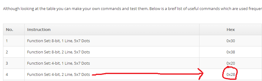
 thanks for input.
Well.. by default LCD gets initialized in 8-bit mode through internal power on reset. So to initialize LCD or put LCD in 4-bit mode LCD needs a software reset. So that 0x30 three times is the reset sequence only after which you can set the data bus width of LCD. I have given link for LCD controller datasheet (HD44780) used in these alphanumeric LCDs which clearly explains this reset sequence. I will update tutorial with this additional information. Will be helpful for others too.
You need to know base timer clock for your timer module. e.g. if you timer module is using 1Mhz clock, it means timer will be incremented by 1 count every 1/1000000 sec = 1uS
Is it a software thing or a hardware thing? Or it is related to crystal frequency? Can I see it in ARM LPC2138 datasheet.
[ Edited Sat Feb 08 2014, 06:53 am ]
If you have not changed the APB divider register then default APB_DIV is 00 which is PCLK = CCLK/4
Hope you get your answer now? and hopefully learned how to see datasheet?


