CAN protocol circuit diagram
Discussion in "ARM Development" started by shruv_emb May 8, 2014.


Thu May 08 2014, 12:02 pm
Hello Everyone!
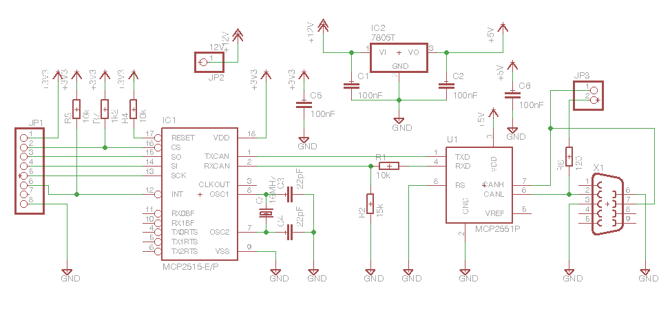
Can someone give me a link or a pic of the exact circuit diagram to connect lp2148 to mcp 2515 (can controller) then connect it to mcp2551 (transceiver). All I can find are block diagrams.
Can someone give me a link or a pic of the exact circuit diagram to connect lp2148 to mcp 2515 (can controller) then connect it to mcp2551 (transceiver). All I can find are block diagrams.


Fri May 09 2014, 10:45 am
Thank you. Different circuit diagrams on the net was confusing,osc circuit and reset circuit are given in the mcp2515 data sheet,will look into it too.
Fri May 09 2014, 12:28 pm
Its always best to go with typical application circuit provided in datasheet. You can also take a look at application notes of this Can controller if available on microchip's website. I am sure it will be very helpful.
Powered by e107 Forum System

scaneraNom
Sat May 04 2024, 02:21 am

gtaletrzua
Fri May 03 2024, 10:55 am

Clydehet
Wed May 01 2024, 06:44 pm

Davidoried
Wed May 01 2024, 06:11 pm

KevinTab
Sun Apr 28 2024, 05:35 am

Tumergix
Sun Apr 28 2024, 12:59 am

StevenDrulk
Sat Apr 27 2024, 08:47 pm

StephenHauct
Sat Apr 27 2024, 09:38 am